
Many thx for DJ0IP (Rick) & ARRL for contribute this subject!
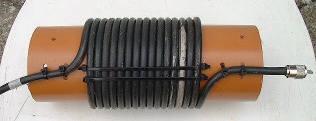
(A) Coiled Coax Choke
The coiled coax choke is the easiest to make but also the least effective. If it works, use it. Otherwise use something better. what is an rf choke
For details see the ARRL HANDBOOK or ARRL ANTENNA HANDBOOK.
Scrambled-Wound Choke? OK or not?
I honestly do not know for sure. I have heard that although it will work, it doesn’t work as well as when keeping the turns in a straight row. I have also heard that on 160m it doesn’t matter; scrambled is OK. It seems to me you could have unwanted, stray coupling if you scramble the turns.
Until I find out for sure, I will continue to wrap my turns in a straight line as shown in the picture (A) above.
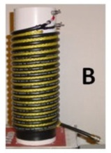
(B) Improved Coaxial Choke
This is a very simple choke to build. The material costs are low, and it is very rugged. You won’t burn this one up.
GOOD OR BAD?
You hear success stories with this choke, but you also hear unfavorable reports about them
What is the truth?
The reality is, this is a good method of building a choke but it does not have a broad bandwidth that chokes wrapped on ferrite have. You can’t build one and expect it to work from 160 thru 10m. When you build one, you need to decide which bands you want it to cover.
How much impedance must a good choke have?
In most cases, 1K Ohms is enough. If the problem with CMC is not severe, you can usually get by with just 500 Ohms. It is difficult to measure Common Mode Current, but it is not difficult to understand that the more imbalance in your antenna, the more CMC you’re going to have.
Here are some basic indicators:*
- A symmetrical dipole or beam fed with coax, but without a balun will have a little CMC on the line. Usually 500 Ohms will be enough impedance for these antennas.
- An asymmetrical antenna, such as an Off-Center-Fed dipole (sometimes called “Windom), will have more CMC on the line and needs a better choke (1K Ohm). Note: OCF dipoles are usually fed 1/3 of the way from one end, causing the additional imbalance.
- Some OCF antennas have an even more drametic feedpoint offset, with the feedpoint located just 20% (or less) away from one end. Feeding like this can increase the number of bands the antenna covers, but it also significantly increases the CMC. Here you need about 2K Ohms.
*Any antenna can incur additional imbalances if there are conducting objects in near proximity of one of its sides. In that case you may need more impedance than shown above.
Especially above 7 MHz, if you use more turns than necessary, the chokes performance will degrade. You can get a graphical view of this by studying the chokes at the bottom of the chart on Steve Hunt’s (G3TXQ) website. See: http://www.karinya.net/g3txq/chokes/
Here are some general guidlines for winding coax chokes on a 10cm (4 in.) PVC pipe,
using RG-58 for low power or RG-213 for high power:
- 160m: 28 turns
- 80m: 24 turns
- 40m: 14 turns
- 20m: 8 turns
- 15m: 5 turns
- 10m: 4 turns
As stated above, it is best to space the individual windings by about 6mm (1/4 inch) using nylon rope between the windings. For more exact details see the link to G3TXQ’s website shown just above the chart.
NOTE: When used with antennas with a lot of Common Mode Current, this “Ugly Balun” is not the best solution. In that case a 1:1 Guanella balun would be far more effective! See “D” (below).
GUIDELINES:
Note: Until I update this with guidelines, here are two good sources for these simple chokes.
Choke Kits:
- 80 – 10m: THE WIREMAN Model 8231
- 160 – 10m: THE WIREMAN Model 8232
These cost about $20 and are very simple to build in about 30 minutes.
For $10 more you can buy them already built (8331 and 8332).
In Germany:
- 160 – 10m: DX-WIRE “Wide Band Mantelwellen Sperre”
- 160 – 10m: DX-WIRE “Low Band Mantelwellen Sperre” (better on 160/80m).
Both cost 34 EURO.
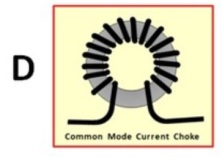
(D) Toroid CMC Chokes . . . (Guanella)
This is a very effective type of CMC choke and very easy to build.
There are two ways to build these:
- Nice and neat in a weatherproof case (see below)
- Quick and dirty; just wrap coax through a large Toroid
- For indoor use, a standard Toroid is fine
- For outside, use a Toroid with a layer of Epoxy on its surface, such as the ones from Ferrocube.
When building a Quick and Dirty, simply wrap the end of your coax around the toroid before soldering the PL-259 onto it. Or, if you wish, you may choose to use a short piece of coax, just long enough to create the number of turns you require, plus short stubs on the ends. Simply solder Coax connectors onto the stubs. This would look like the drawing in “D” above, but with two PLs attached.
TWO CHOICES:
- Dirt-Simple – the coax is wound “continuous” in one direction, like in picture D at the top.
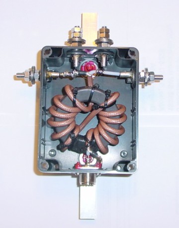
- Simple – the coax is “cross-wound”, like in the picture below.
The cross-wound method (Reisert method) reduces mutual capacitance in the windings, thus improving the common mode impedance significantly.
This method was developed by Joe Reisert, W1JR and named after him. This is the method I always use and is certainly the preferred method. Don’t worry if you wrap the choke like this, reach the end and find that one side has one more turn than the other; that doesn’t matter.
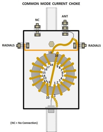
I find it practical to build the CMC choke into a plastic box and include connections for the antenna I will use it for. For instance in the case of a Vertical, I use a box with 5 holes, one for the SO-239 coax jack, and 4 for screws.
- [Top] Screw 1: Top of Choke
- [Top] Screw 2: No Connection. (used when it is necessary to feed the antenna through a capacitor)
- [Side] Screw 3: Radials connection
- [Side] Screw 4: Radials connection
Note: The shield (ground) side of the SO-239 should only connect to the shield of hte coax.
It must not be connected to the radial screws.
All components use for this choke were sourced from Spiderbeam, but this is not a standard Spiderbeam product.
CHOICE OF COAX AND TOROID:
For 160, 80, & 40m, you cannot get enough turns on the toroid using RG-213. RG-58 will work fine, but only for a few hundred watts. For more power, use thin Teflon coax, such as RG-142.
Using RG-142 or RG-58, it is possible to get about 17 or 18 turns onto an FT-240-xx toroid. This is easily enough for 80m and above (but too much for 15, 12, and 10m).
Approximate Impedance on 160m:
- FT-240-61: 500 Ohms
- FT-240-43: 4000 Ohms
- FT-240-31: 4000 Ohms
500 Ohms is just barely enough. Normally it should be enough.
When using a coax connector at the bottom and screws at the top, there is a trick that enables you to keep all of the coil’s windings in the same direction, for instance “clockwise”, but still exit the box on opposite ends. To do this:
- Begin at the bottom near the coax connector, and wrap half of the turns on one side,
- Then drop the coax back down to the beginning
- and wrap the other half of the turns on the other side, taking care that you continue winding in the same direction (clockwise).
When using a coax connector at the bottom and screws at the top, there is a trick that enables you to keep all of the coil’s windings in the same direction, for instance “clockwise.” To do this:
- Begin at the bottom near the coax connector, and wrap half of the turns on one side,
- Then drop the coax back down to the beginning
- and wrap the other half of the turns onto the other side of the toroid, taking care that you continue winding in the same direction (clockwise).
- The picture on the right shows this method of winding, but keep in mind it has only 7 turns per side. For our low band CMC choke, we need about 8 or 9 turns per side.
- TIP: wrap the turns as tight and close together as you can. Use wire-ties to hold the ends in place.